

 English
 Español
 Deutsch
 عربى
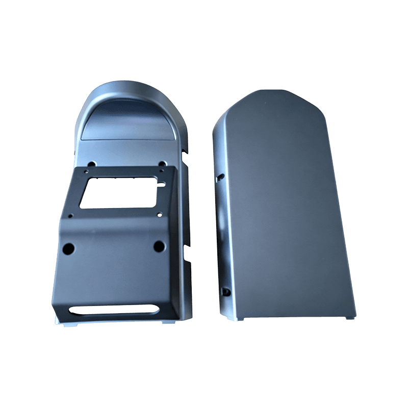
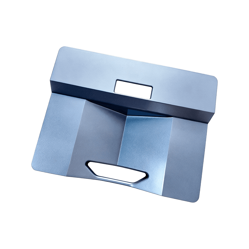
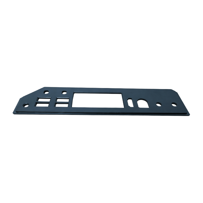
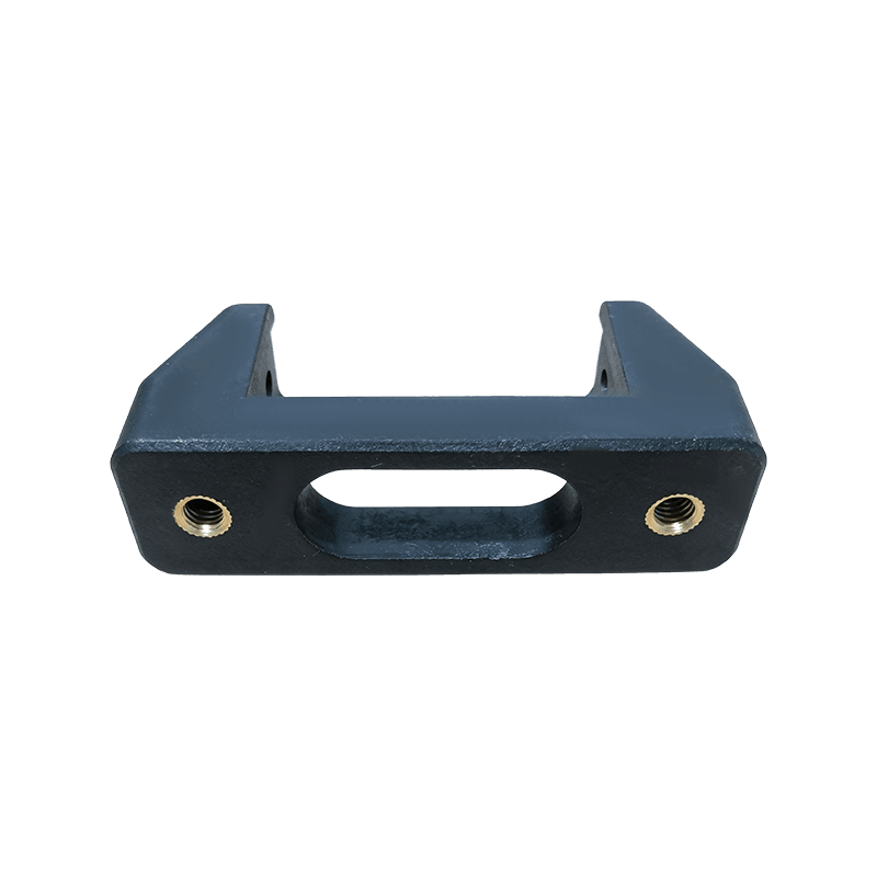
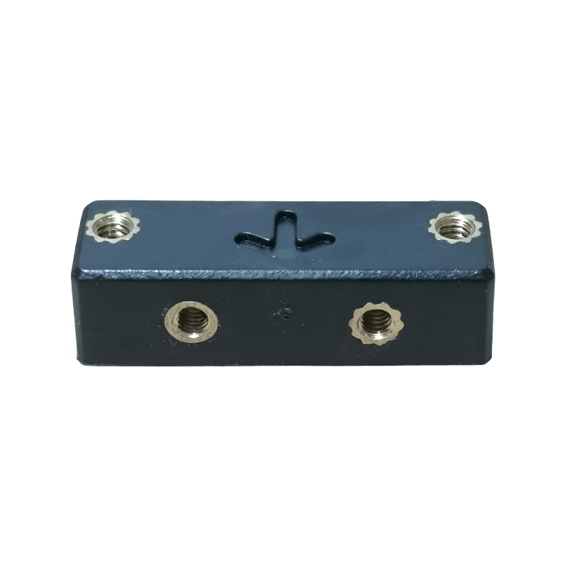
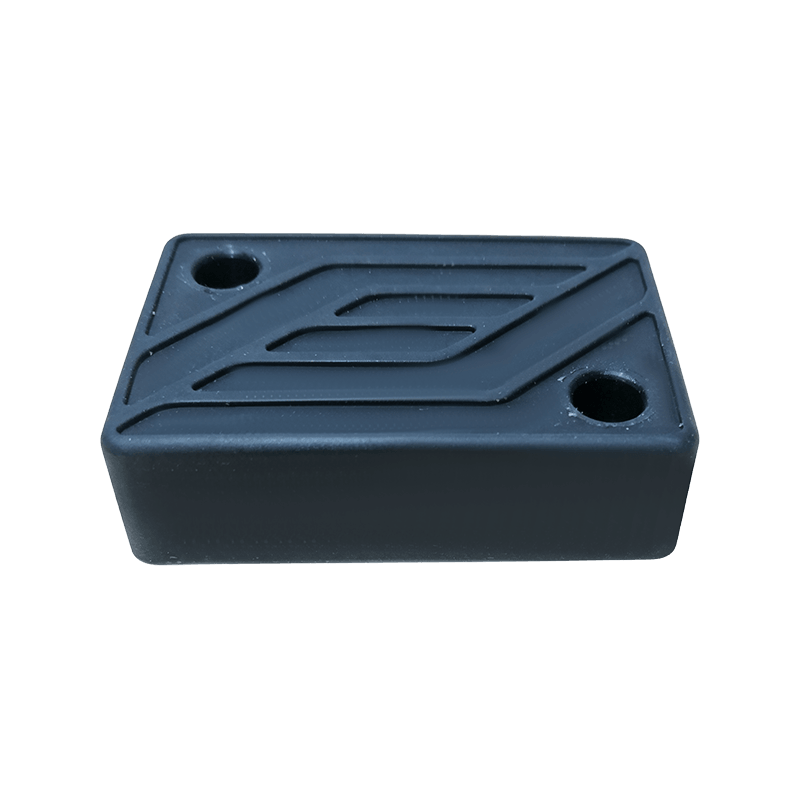

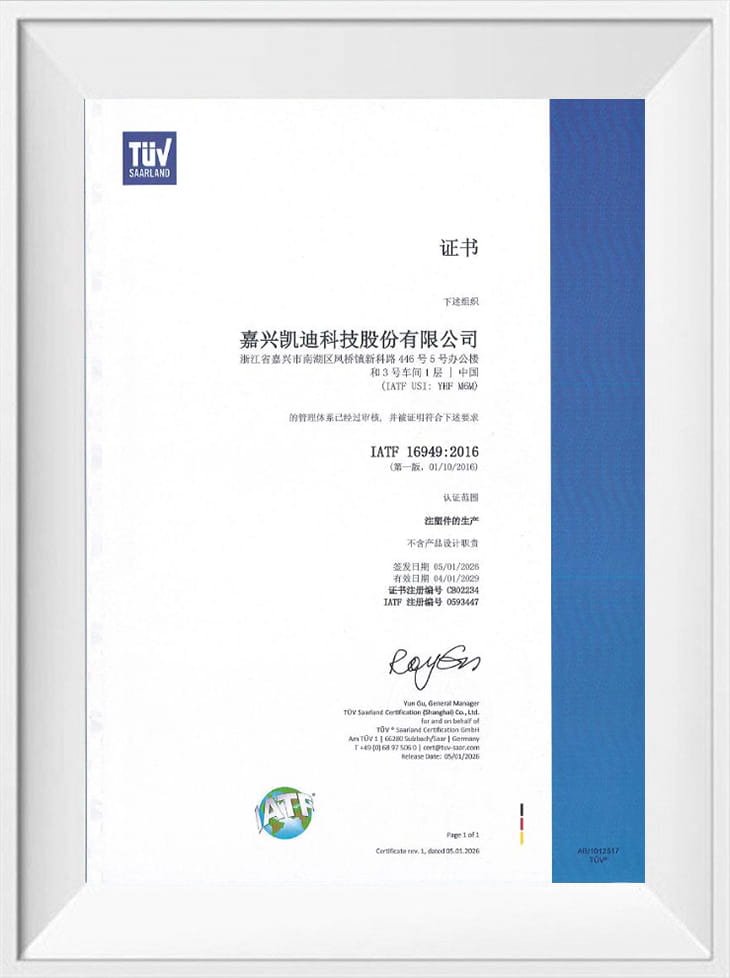
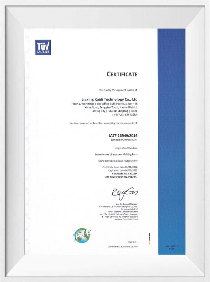
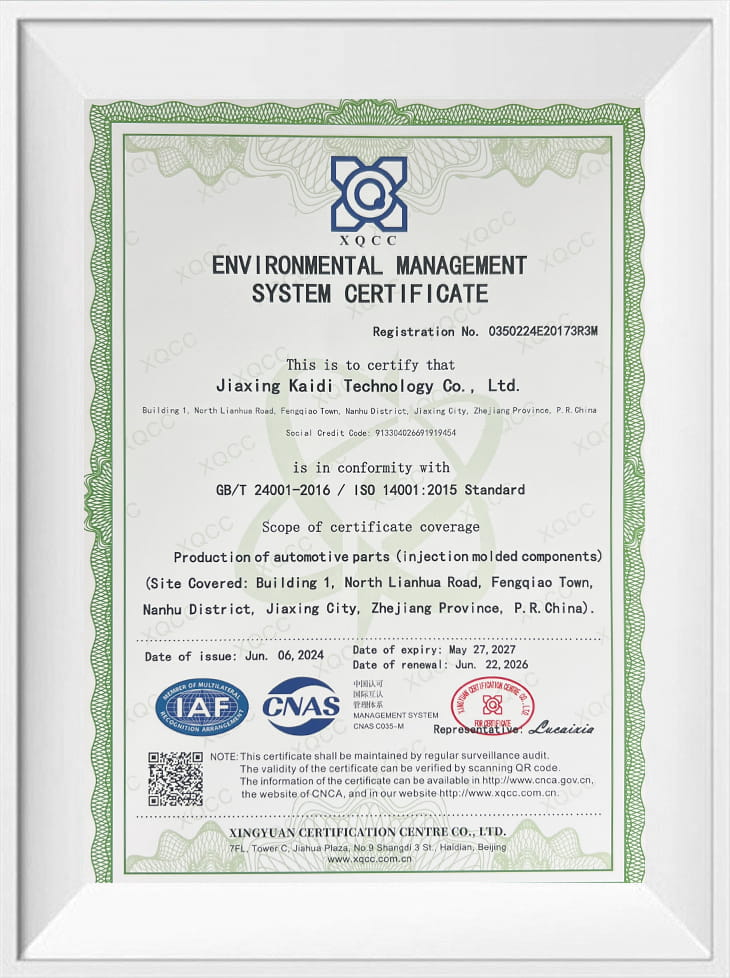
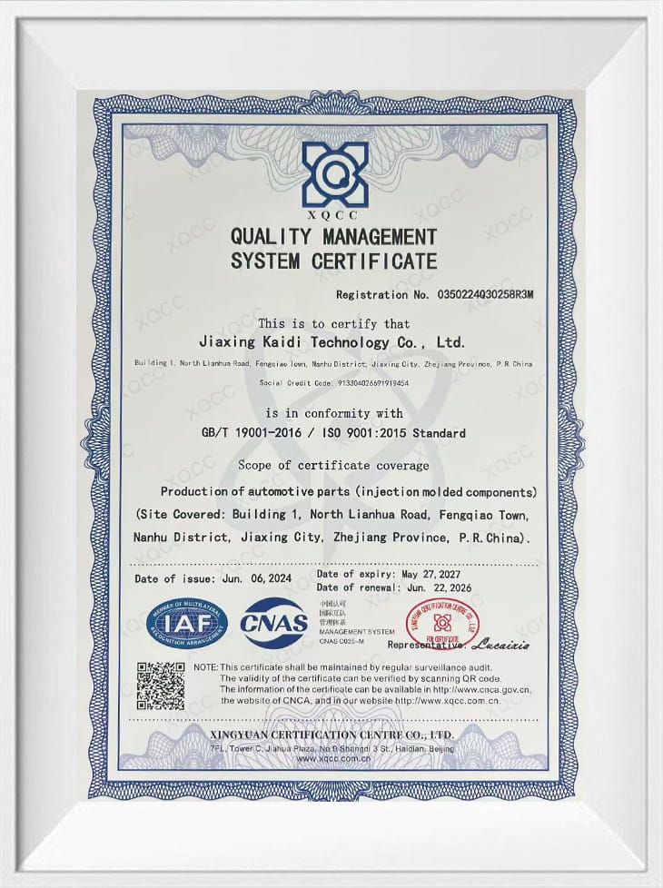

Jiaxing Kaidi Technology Co., Ltd. molds the plastic that sits inside robot platforms and automation equipment: controller front and rear housings, charging-dock front covers, controller enclosures, glass-filled adapters, fixing brackets and silicone contact pads. Tooling, injection molding, spray coating and final assembly run under one roof at our Fengqiao plant in Jiaxing, Zhejiang, so a dock or controller sub-assembly arrives as a matched set of parts rather than a bundle of separately sourced moldings.
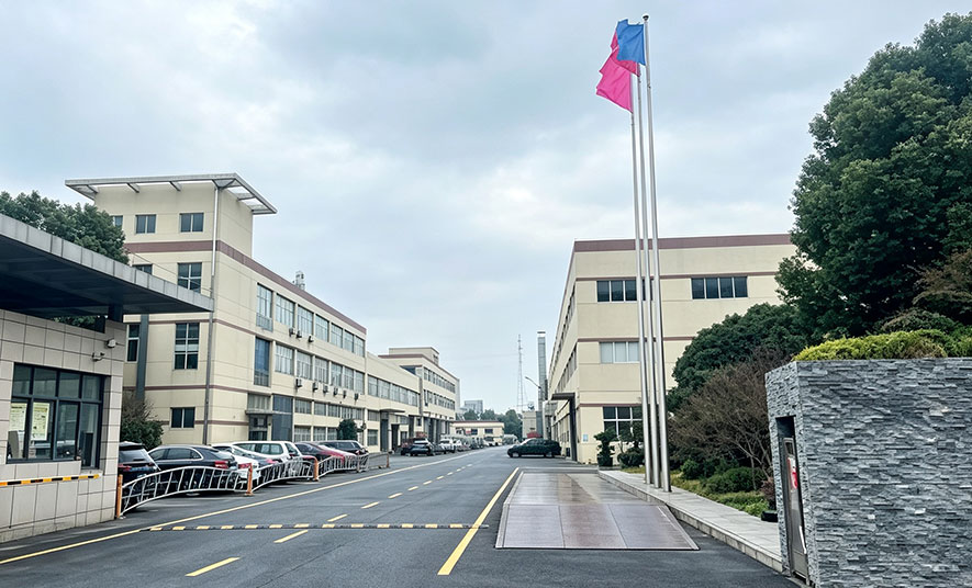
The plant was established in 2007 on a 52-acre site with 35,000 m² of factory floor. More than 100 people work across the injection molding and spraying workshops, over half of them technicians, and annual output is approximately 90 million yuan. Robotics and automation work runs through the same Injection Molding discipline we apply to automotive and appliance programs.
What We Supply as a Robotics & Automation Components Manufacturer
The range covers the parts that carry an enclosure, hold a docking interface or transfer load into a robot chassis. Each family is tooled around its own set of controls — a visible cover raises appearance questions that a hidden bracket does not, and a reinforced adapter raises weld-line questions that a PC+ABS cover does not. We build the Robotics & Automation Components manufacturer program around that split.
| Component family | Typical substrate | Function in the equipment | Primary control focus |
|---|---|---|---|
| Controller front and rear housings | PC+ABS | Operator-facing enclosure for the robot controller board | Wall balance, boss and snap integrity, connector cut-outs, appearance |
| Charging dock front housing | PC+ABS | Visible docking face on AGV, AMR and service robots | Interface alignment, draft, sink control on visible surfaces |
| SRC-2500CEB plastic enclosure | PC+ABS | Controller and power enclosure shell | Flatness, corner strength, dimensional stability |
| Charging dock adapter | PA66+GF30 | Load-bearing interface between dock body and base | Glass-fibre dispersion, weld-line strength, creep under sustained load |
| Charging dock fixing bracket | PC+ABS | Internal retention of the dock module | Screw-boss torque, stiffness, warpage |
| Charging dock cushion pad | Silicone | Contact and damping pad under the dock or robot foot | Shore hardness, compression set, fit to the molded recess |
Visible housings such as the PC+ABS robot controller front and rear housings are ordinarily produced as a front and rear pair on matched tools, so the mating step, the screw tower heights and the connector openings are dimensioned against each other from the first trial.
Substrate Selection: Where Each Material Fits
Material choice in this category is decided by the load path and the appearance requirement, not by a single preferred grade. We confirm the substrate against the drawing, the assembly method and the environment the robot operates in.
- PC+ABS — the default for controller housings, enclosures and visible dock covers. It balances impact resistance with dimensional stability across the wall sections used on hand-held and enclosed electronics, and it takes UV and matte/high-gloss coating systems.
- PA66+GF30 — used for adapters and load-bearing interfaces where stiffness and creep resistance matter more than surface finish. Glass-fibre orientation controls gate position, and weld lines must be kept out of the highest-stress section.
- Silicone — specified for cushion pads where compliance, grip and compression set are the functional requirements rather than rigidity.
- ABS and PP — practical where brackets, frames and internal carriers need toughness and paintability without the full PC+ABS cost position.
Critical Specifications We Tool and Inspect
Robotics components fail at interfaces before they fail anywhere else. The tolerances that carry the most weight in our process control are the ones that decide whether a board drops into a housing and whether a dock seats against its adapter.
- Interface alignment between mating housings, dock faces and adapter seats
- Boss and snap-fit integrity, including boss diameter, depth and snap undercut geometry
- Connector and cable clearance behind the housing wall, with routing space preserved
- Dimensional stability across the tool life and across material lots
- Appearance consistency on A-surfaces: flow marks, weld lines, sink and colour
- Flatness of mounting and mating faces where the part is screwed to a metal frame
- Thread-forming and screw-boss performance under repeated assembly
DFM, Moldflow and Tooling Approach
Our DFM review concentrates on wall balance, rib and boss geometry, undercuts, draft and the critical interfaces named on the drawing. Fill and packing simulation is used to locate weld-line and air-trap risk before steel is cut, which is where most appearance and strength disputes on reinforced adapters are actually settled. Tool construction follows the projected volume and the finish requirement, with the Industrial & Robot Molds program covering the robot-specific tooling side of the same project.
Designers on our team carry more than ten years of mold design experience in automotive and small-appliance work, a background that transfers directly to enclosed electronics where tolerance stacks and cosmetic surfaces meet on the same part.
Coating, Assembly and Delivery Scope
Housings that are seen by an end user usually leave our plant coated rather than raw. UV coating, matte and high-gloss systems are applied in the spraying workshop, and two-color molding is available where a housing needs a differentiated colour zone or a soft-touch element in a single tool cycle. Assembly scope is agreed per project: silicone pads bonded or located into molded recesses, brackets fitted, mating pairs packed as sets.
Delivery scope, packaging format and identification are confirmed against the assembly sequence at the customer end, so parts arrive in the condition the line needs rather than in the most convenient shipping format.
Quality Checks and Acceptance
Inspection is built around the characteristics that the customer's assembly actually consumes. Our measuring room and instrument set support first-article dimensional reports on critical interfaces, in-process checks during molding, and appearance review against an agreed boundary sample for visible housings.
- First-article inspection on interface, boss and connector features
- In-process dimensional and visual checks at defined intervals
- Material verification against the specified grade, including glass content on reinforced parts
- Coating appearance and adhesion checks on painted housings
- Assembly and fit checks on pad, bracket and housing combinations
- Mold maintenance records and tooling condition tracking across the production life
Information We Use to Configure Your Solution
A robotics component quotation is only meaningful when it is tied to the interfaces and the production target. This is the input set we work from; where an item is still open, we flag it in the DFM response rather than pricing around an assumption.
| Project input | What it determines in our proposal |
|---|---|
| 3D CAD and 2D drawing with GD&T on interfaces | Tool layout, parting line, tolerance allocation and inspection plan |
| Mating hardware: PCB outline, connector positions, screw bosses, mating faces | Clearance design, boss geometry and fit verification method |
| Substrate and finish specification | Material grade, gate position, coating system and appearance standard |
| Annual volume, launch ramp and variant count | Cavitation, tool construction and two-color or single-color process route |
| Assembly content: pads, brackets, mating pairs, sub-assemblies | Assembly scope, packaging format and delivery condition |
| Acceptance criteria and required documentation | Inspection frequency, report format and boundary samples |
| Operating environment and target markets | Material and coating selection constraints, plus test requirements to be agreed |
Frequently Asked Questions
Can you mold a controller housing around our existing PCB and connector layout?
Yes — that is the normal starting point. We work from your board outline, connector positions and screw locations, then design standoffs, cable routing space and connector openings around them. Clearance to the housing wall is confirmed in DFM before tooling, and the first trial checks that the board seats without stressing the connectors.
Should a load-bearing charging dock adapter be PC+ABS or PA66+GF30?
It depends on whether the interface is dominated by impact or by sustained load. PC+ABS is the better fit where the adapter also forms part of the visible surface or absorbs knocks during docking. PA66+GF30 is the choice where the adapter carries continuous load or forms a screwed structural joint, and in that case we position gates and verify weld-line location so the reinforced material performs where the stress actually is.
Do you supply the complete dock module, including the silicone pad and bracket?
We mold the PC+ABS front housing, the PA66+GF30 adapter, the fixing bracket and the silicone cushion pad, and we assemble them into a matched module where the scope calls for it. Housing pairs are dimensioned against each other from the same tooling release, which removes the fit problems that appear when covers and adapters come from separate suppliers.
How do you control appearance on visible robot housings?
Cosmetic surfaces are defined as A, B or C areas on the drawing, and gate positions plus wall transitions are set to keep flow marks and sink out of the visible zones. Coating adds a further step: matte or high-gloss systems are applied in our spraying workshop, and appearance is judged against an agreed boundary sample rather than a verbal description.
