
 English
 Español
 Deutsch
 عربى
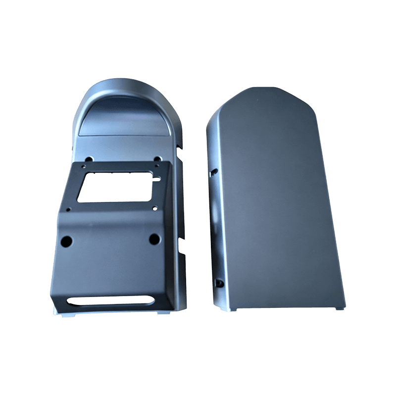
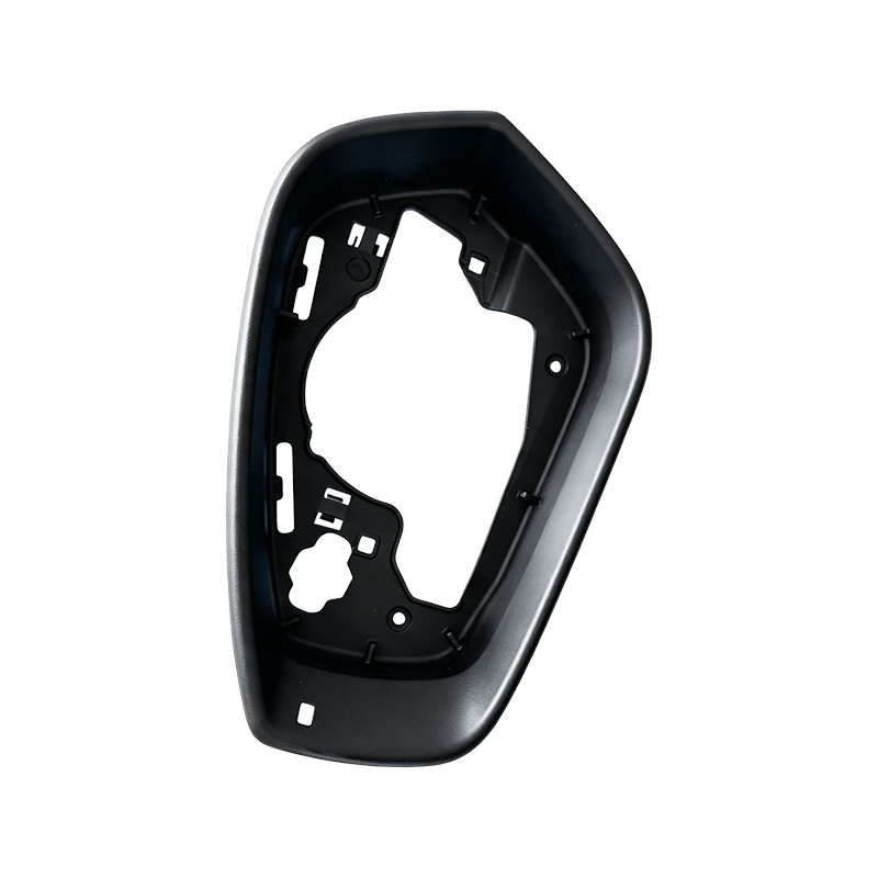
Controlling warpage starts before mold construction. For large plastic covers and panels, the design, resin, tool, molding process and handling conditions must support the same agreed shape and assembly requirements.
A molded panel may look acceptable when it leaves the machine yet show an uneven edge during assembly. A cover may sit correctly at one mounting point while lifting at another. For automotive trim, motorcycle panels and equipment housings, these deviations can affect both appearance and function.
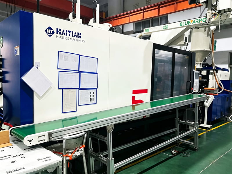
Solving the problem requires more than adjusting a machine setting. Buyers and manufacturers need to define the defect consistently, examine its likely causes and validate improvements under representative conditions.
1. Understand Why Large Covers Reveal Shape Variation
Warpage is a departure from the intended shape, such as bowing, twisting or lifted edges. Across a broad surface or long mating edge, even a modest change in curvature can become noticeable during installation.
The practical concern depends on the application. A decorative panel may be judged by the gap around its perimeter, while an equipment cover may depend on mounting alignment and clearance around internal components.
Describe the actual failure instead of reporting only that the part is warped. Photographs, marked measurement locations and an assembly illustration help the supplier investigate a specific problem rather than an undefined visual impression.
2. Define Acceptable Shape and Measurement Conditions
Identify the required flatness, profile or assembly gap using suitable drawing requirements. A curved panel should follow its intended contour; it should not be assessed against an unexplained expectation of being flat.
Mark the datums, mounting points and critical visible edges. Agree whether measurements apply to the free part, a defined fixture or the installed assembly. Record support positions and fastening conditions so both parties evaluate the component consistently.
Also specify when measurements are taken after molding and any relevant conditioning requirements. Comparing a warm sample immediately after ejection with a stored sample can confuse the investigation. Acceptance should reflect an agreed delivery or use condition.
3. Review Wall Distribution and Structural Balance
Start the design review with wall transitions, local thick regions, ribs, bosses and perimeter structures. Uneven sections can create different cooling and shrinkage behavior across the component.
Assess whether the reinforcing features provide the required stiffness without concentrating material unnecessarily. A heavy rib arrangement on one side of a broad panel may introduce a different risk from a more balanced layout.
Do not add thickness everywhere as a default remedy. Review stiffness, weight, surface quality and moldability together. Where a change is proposed, check its effect on adjacent features and mating components before releasing the revised design.
4. Select the Resin for the Complete Application
Use the specific resin grade, not simply the polymer family, when reviewing dimensional behavior. Consider the supplier's material data alongside operating temperature, stiffness, impact and appearance requirements.
Reinforcement can change both stiffness and shrinkage behavior. In fiber-filled grades, orientation can produce different shrinkage in different directions. A stiffer material therefore does not automatically provide a less warped component.
Follow the grade's preparation requirements and consider moisture-related dimensional changes where relevant. If the material or reinforcement level changes, review the implications for tooling, processing and validation. An apparently equivalent substitute should not inherit dimensional approval without assessment.
5. Evaluate Gates, Cooling and Ejection Before Tool Build
The mold review should connect filling, packing, heat removal and part release. Gate placement affects flow paths and, for reinforced materials, orientation. Cooling arrangements need particular attention around thick features, deep structures and areas that are difficult to reach.
Review both mold halves and local sections rather than assuming a suitable coolant setting guarantees a uniform mold surface temperature. Include the planned ejection and support arrangement in the discussion.
Simulation can compare proposed gate layouts, cooling conditions and predicted deformation. Treat the results as engineering evidence with stated material inputs and assumptions. Compare predictions with trial results before relying on them for final acceptance.
6. Establish a Repeatable Molding Process Window
During trials, record material preparation, filling, packing and cooling conditions together with the measured outcome. Check whether the distortion repeats consistently or varies between samples. That distinction helps determine the next investigation step.
Use a structured trial plan rather than changing several unrelated conditions without a record. Keep the measurement method and sample conditioning consistent, and evaluate whether an improvement persists across consecutive parts.
Review the complete part quality after each meaningful change. A condition that improves one edge but creates flash, surface defects or dimensional problems elsewhere is not a complete solution. Production release should rely on a workable process range, not an isolated acceptable sample.
7. Check What Happens After the Mold Opens
Part release and downstream handling belong in the investigation. A component removed before it has sufficient rigidity can deform, particularly if ejection or handling loads are concentrated.
Observe how the panel is removed, transferred and placed. Check whether unsupported edges, stacking loads or contact points change its shape. A controlled comparison between normally handled samples and individually supported samples can help isolate a handling contribution.
For painted parts, compare shape before and after the finishing route. Review curing conditions, fixtures and cooling after finishing. Then inspect packaging and storage arrangements so a satisfactory molded component is not distorted during later operations.
8. Validate Improvements Against the Real Assembly
Use representative mating components or an agreed inspection fixture to check the locations that matter: mounting points, long edges, visible gaps and clearances. Keep the component revision, material and finishing condition traceable.
Assembly inspection should complement individual-part measurements. Where normal fastening is intended to locate a flexible cover, define the permitted installation method. Excessive force or distortion of surrounding parts should not become an informal acceptance practice.
For the agreed validation scope, compare samples across relevant production runs and environmental conditions. Record results before and after corrective action, identify remaining limitations and obtain approval against the defined requirements.
If a fixture, secondary operation or changed packing method is needed to maintain acceptance, document it in the production scope. Buyers should understand any effect on cost, capacity, inspection and delivery before approving the solution.
A Practical Warpage Review Checklist
| Review stage | What to confirm |
|---|---|
| Product requirements | Intended contour, critical datums, allowable deviation and measurement condition |
| Part design | Wall transitions, ribs, bosses, thick regions and structural balance |
| Material | Approved grade, shrinkage behavior, reinforcement and conditioning needs |
| Mold design | Gate layout, local cooling, release features and ejection support |
| Molding trials | Recorded conditions, repeated measurements and effects on other defects |
| Downstream operations | Handling, painting, support, stacking and storage |
| Final validation | Representative assembly checks, packaging protection and release approval |
Review Warpage Risk Before Committing to Tooling
Provide the large-part model together with the mating information, key shape requirements and intended operating conditions at the inquiry stage. Ask the supplier to identify likely risk areas and propose a validation plan before tool construction.
Kaidi combines mold making, injection molding, surface painting and assembly support for custom plastic components. For covers and panels, reviewing these stages together helps define the investigation and inspection scope across the manufacturing route.
Share available drawings and assembly references early. Clear acceptance conditions and a documented review give both buyer and manufacturer a stronger basis for evaluating samples and approving repeatable production.