

 English
 Español
 Deutsch
 عربى
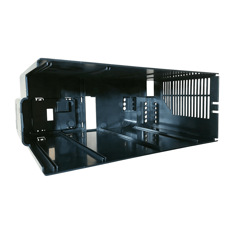
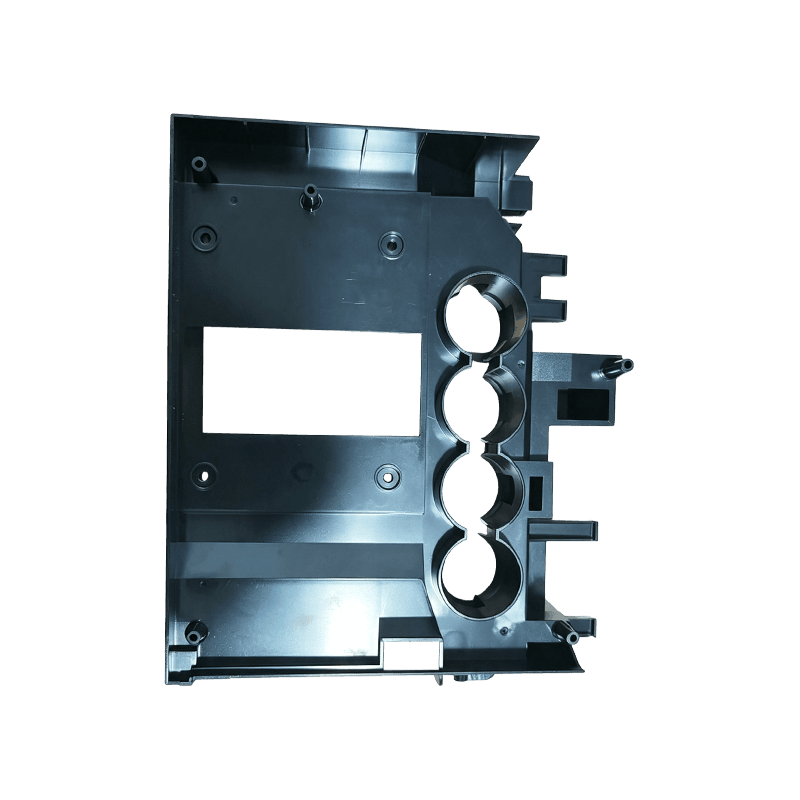

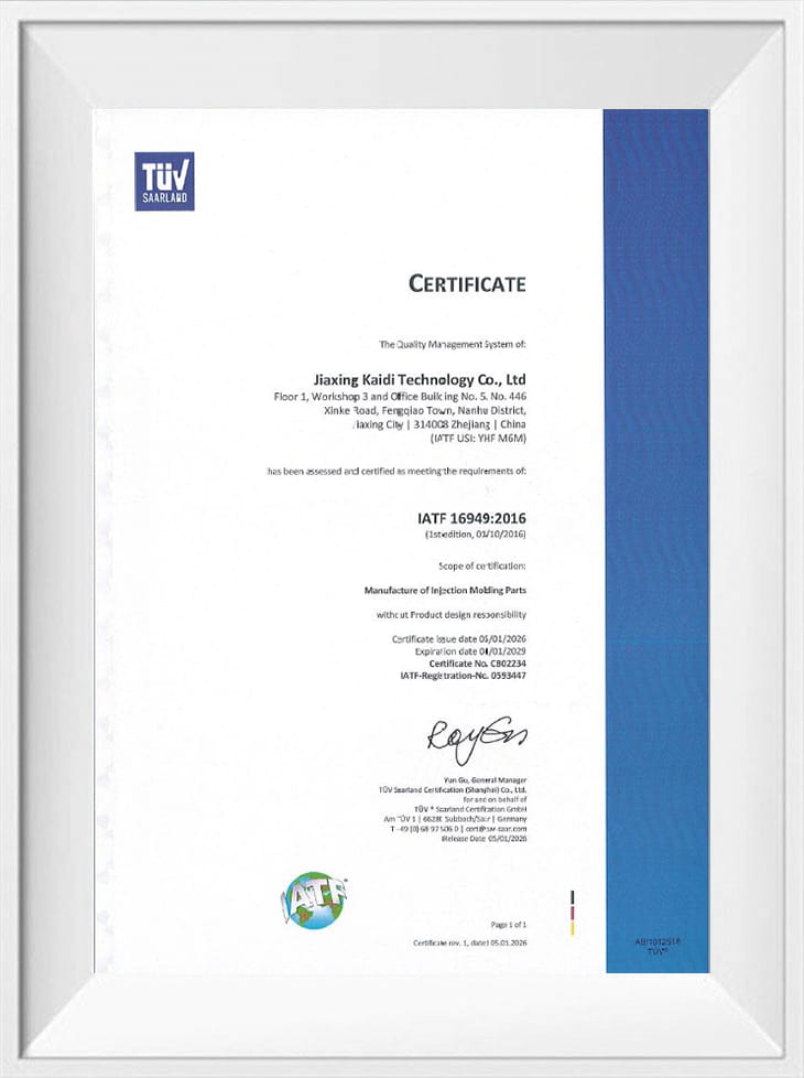
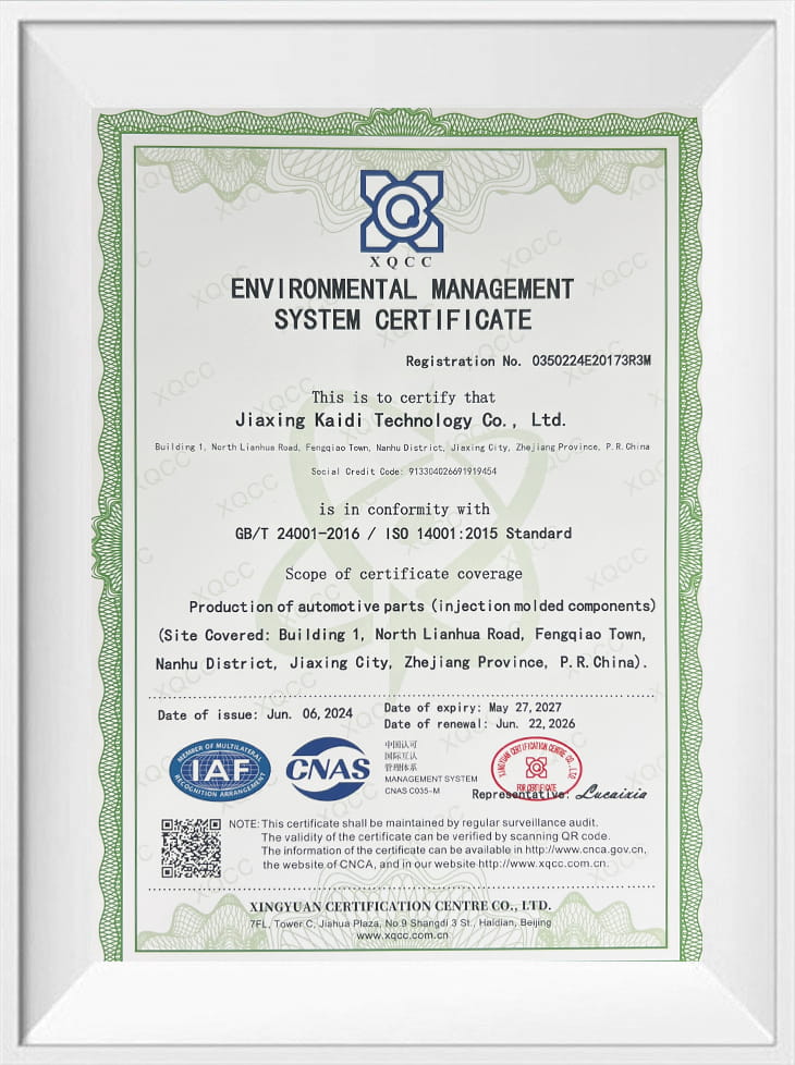
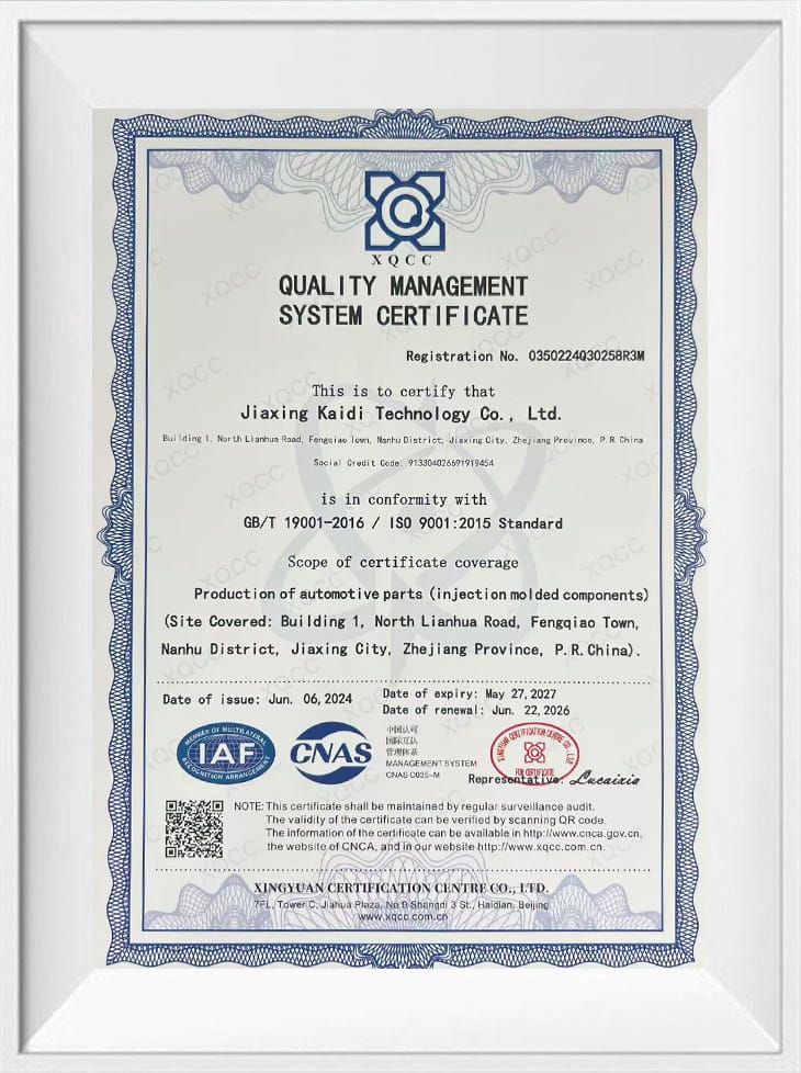

Jiaxing Kaidi Technology Co., Ltd. molds custom plastic parts for home and electrical appliances: center frames, support brackets, housings, bezels, covers and internal trim in ABS, PC+ABS, PP, PC and glass-filled PA66. We are an OEM Home & Electrical Appliance Parts manufacturer working from Jiaxing, Zhejiang, China, and we run tooling, molding, spray painting and finished-product assembly as one chain, so a structural bracket and the painted cover that sits over it are produced and checked together.
The range is built around parts that carry load, locate other components or face the end user. Frames and brackets have to hold tolerance through repeated assembly; visible covers and panels have to hold color and gloss batch after batch. Our engineering work therefore starts on the drawing, before steel is cut.
Appliance Parts in Our Current Range
Appliance work sits between precision structural molding and appearance molding. The same program usually contains both, which is why we keep mold making, molding and painting in-house rather than splitting them across suppliers.
- Center frames and chassis frames — the load-bearing skeleton of a unit, with boss patterns and ribs that locate motors, boards and panels.
- Support brackets and mounting plates — small, tolerance-critical parts that fix sub-assemblies and take vibration or static load.
- Housings, control boxes and enclosures — walls, ribs and snap features with connector cut-outs and screw bosses.
- Bezels, panels and visible trim — textured or painted covers where gloss, color and sink-mark control decide acceptance.
- Internal mounts, clips and spacers — low-cost functional parts where warp and gate position still matter for fit.
A representative program part is our Custom ABS Appliance Center Frame, molded in ABS with the rib and boss layout reviewed against the mating components before tooling; the custom ABS appliance support bracket follows the same DFM route on a smaller, flatter section.
Material Choice Drives the Part
Resin selection decides wall sections, gate position, drying routine and paint route, so we settle it with the customer's engineering team at quotation stage rather than after mold trial. The matrix below reflects the grades we process most often for appliance parts.
| Material | Typical appliance parts | Engineering reason | What we check in DFM |
|---|---|---|---|
| ABS | Center frames, support brackets, housings | Balanced stiffness and impact, good paint take-up, predictable shrinkage | Gate location, weld lines at bracket junctions, adhesion on textured faces |
| PC+ABS | Bezels, control housings, visible covers | Higher impact and heat resistance than ABS with good surface quality | Pre-drying, melt window, molded-in stress around bosses |
| PP | Internal ducts, tanks, hinge sections, non-visible structure | Chemical resistance, living-hinge capability, low material cost | Shrinkage allowance, warp on long flat sections, paint limitation |
| PC | Transparent covers, light windows, heat-exposed housings | Clarity and toughness at elevated temperature | Moisture control, gate-free optical zones, residual stress |
| PA66+GF30 | Load-bearing brackets and mounts near heat sources | High strength and stiffness, dimensional stability under load | Fiber orientation, gate position versus load direction, tool wear |
Grades with flame-retardant or glow-wire requirements are processed to the nomination on the drawing, with the material file reference recorded in the project documentation so the molding, the marking and the certificate trail stay aligned.
DFM Review Before Tooling
Every appliance tool starts with a design-for-manufacture review that returns a marked-up model and a written report. The review concentrates on the features that cause scrap later: uneven walls, ribs that pull sink into a visible face, insufficient draft on textured surfaces, ejector marks on class-A panels, and gates placed where a weld line will land in the wrong place.
- Wall thickness and transition geometry, including bosses and screw columns
- Rib and boss layout against sink-mark risk on visible faces
- Draft angles and shut-off condition for textured or painted surfaces
- Gate position, fill balance and weld-line location
- Ejector layout versus cosmetic and assembly-critical zones
- Two-color, insert or assembly features that constrain tool design
Tooling is built through our Appliance & Consumer Molds group, where mold designers work from small-appliance experience. The mold trial then establishes the process window that will be locked into the production setting sheet, and the first-article dimensions are measured against the drawing in our measuring room.
Painting, Coating and Assembly
Visible appliance parts frequently ship painted rather than raw, and keeping that step in-house removes the handling and re-packing that usually damages class-A surfaces. Our spraying workshop handles UV coating and matte or high-gloss finishes, with masking planned at the tooling stage so paint edges land on a defined geometry instead of a hand-cut line.
- UV-cured clear coats for scratch and chemical resistance on touch surfaces
- Matte and high-gloss topcoats matched to a supplied color chip
- Two-color molding for parts that would otherwise need a second paint operation
- Assembly of frames, brackets, inserts and covers into a delivered sub-assembly
Finishing detail for appliance and electronics work is set out under Electronics & Appliance Painting, including the zones we mask and the gloss readings we record per surface.
Specifications and Acceptance
Acceptance is agreed as a written characteristic list before the first shot, not negotiated after parts arrive. The table shows the categories we normally fix at that stage.
| Characteristic | What we agree | How it is confirmed |
|---|---|---|
| Critical dimensions | Datum scheme, tolerances and assembly-critical features from the drawing | First-article dimensional report, plus fixture or gauge checks on mating features |
| Color | Physical chip or master sample for molded and painted surfaces | Comparison under the agreed light source against the retained sample |
| Gloss | Target range per surface zone, textured areas defined separately | Gloss meter readings recorded by zone on the inspection sheet |
| Appearance | A/B/C surface classification with defect limits per zone | Visual standard samples retained at the press and in final inspection |
| Fit and function | Mating parts, inserts or gauges supplied for the trial | Trial assembly at the machine and again after painting |
| Paint performance | Test method and acceptance criteria from the customer's standard | Testing on trial parts before mass production release |
| Packaging | Part protection, carton configuration and labeling format | Packaging trial approved before the first shipment |
Information We Use to Configure Your Solution
A quotation we can stand behind is built from production data, not from a part name. These are the inputs that let us price the tool, the molding and the finishing correctly the first time.
- 3D model in STEP or IGES plus a 2D drawing with datums, tolerances and marked critical characteristics
- Resin or grade nomination, color code, and any regulatory file reference your market requires
- Annual volume, batch size and shipment pattern, including whether parts ship as moldings, painted parts or assembled units
- Surface zoning: which faces are visible, texture specification, gloss target and masked areas
- Mating parts, inserts, fasteners or gauges the part must work with
- Packaging and labeling standard, and the delivery scope expected per shipment
- Acceptance criteria for the first article and any incoming inspection plan on your side
- Program dates and tooling milestones that affect the mold build sequence
Frequently Asked Questions
Can you supply complete painted and assembled appliance sub-assemblies?
Yes. Molded parts, painted covers and assembled frames can be delivered as one item, which is how most of our appliance programs run. Masking, paint and assembly steps are planned at the DFM stage so the painted edges and the assembly sequence match the tooling rather than being corrected afterwards.
How do you handle warp on long, flat appliance panels?
Warp is addressed in the tool and the process together: gate position and fill balance first, then cooling layout, then packing profile at the press. For PP and ABS panels we agree the flatness measurement method and support points with the customer, because the reading depends heavily on how the part is restrained when it is checked.
What happens to the mold after the program ends?
Tooling is maintained in our mold maintenance workshop, where wear items, ejector systems and cooling channels are serviced between production runs. Maintenance records and tool condition notes travel with the program, and we discuss spare tooling, replacement inserts or duplicate cavities when volumes justify them.
Do you support two-color molding for appliance control parts?
Two-color injection is part of our process lineup and is normally proposed where a hard structural substrate is combined with a soft-touch grip, a sealed button area or a decorative ring. We review the material pairing, the bond interface and the first-shot shrinkage before committing to a two-shot tool.
