

 English
 Español
 Deutsch
 عربى


Industrial & Robot Molds From a Single In-House Chain
Jiaxing Kaidi Technology Co., Ltd. builds Industrial & Robot Molds for the plastic structures that sit inside service robots, automated handling equipment and industrial housings: controller enclosures, charging dock assemblies, mounting brackets, structural frames and covers. Toolmaking is one stage of a continuous in-house chain — precision mold manufacturing, injection molding, spray coating and finished-product assembly — so a tool is planned from the first concept against the resin, the molding window and the surface the finished part must carry.
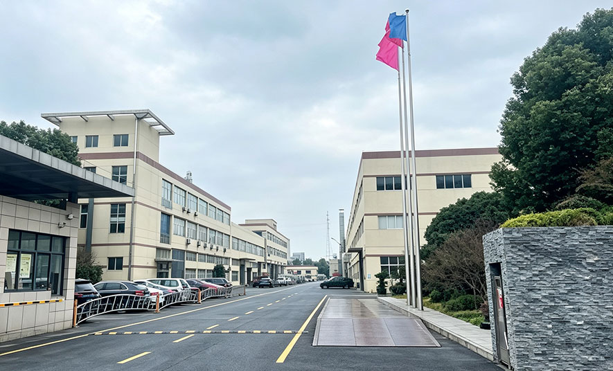
Established in 2007 on a 52-acre site with 35,000 ㎡ of factory floor, our injection molding and spraying workshops employ more than 100 people, over half of them technicians. That mix of toolmakers, process engineers and finishing staff is what allows an Industrial & Robot Molds manufacturer to close the loop between mold design decisions and what actually comes off the press.
Part Families We Tool For
Robot and industrial programs rarely consist of one part. A single machine platform typically needs an enclosure pair, a dock housing, a bracket, an adapter with metal inserts and a sealing or cushioning element. We tool these as a coordinated family so wall-stock strategy, gate position and cosmetic standards stay consistent across the set.
- Controller and enclosure housings — PC+ABS front and rear housings where split-line position, boss alignment and connector cut-outs drive assembly fit.
- Charging dock assemblies — front housings, fixing brackets and adapters, including glass-filled PA66+GF30 grades where stiffness and creep resistance matter more than cosmetics.
- Structural internals — brackets, center frames and support components in ABS and PC+ABS, often with metal insert overmolding and tight flatness requirements.
- Industrial covers and enclosures — larger PC+ABS shells where draft, ejector layout and sink control across deep draws decide the visual result.
- Soft-touch elements — silicone cushion pads and contact parts tooled as compression or dedicated low-volume tools depending on geometry.
Related molded output from these tools is grouped under Robotics & Automation Components, where the finished part rather than the tool is the deliverable.
Our Mold Making Range and Where Each Family Fits
Industrial & Robot Molds is one of three tool families we manufacture. The table below shows how we split the range and which design decisions dominate in each.
| Mold family | Typical parts | Material focus | Tooling priorities we plan in |
|---|---|---|---|
| Industrial & Robot Molds | Controller housings, dock housings, brackets, adapters, enclosures | PC+ABS, PA66+GF30, PC, ABS, PP | Mating interfaces, insert anchoring, weld-line placement, replaceable inserts, cosmetic split lines |
| Automotive Injection Molds | Interior and exterior trim, functional under-hood parts | PP, ABS, PC+ABS, PA | Texture and grain control, painting fixtures, high cavitation for volume |
| Appliance & Consumer Molds | Brackets, center frames, trays, visible covers | ABS, PP, PC+ABS | Family tools, boss strength, appearance consistency across colors |
The full tooling offer, including maintenance and repair of tools already in service, is presented under Mold Making / Tooling.
Material Behaviour Drives the Tool, Not the Reverse
Robot components are rarely plain commodity resin. Glass-filled PA66+GF30 changes shrinkage directionally as fibers align with flow, so gate location is set partly by which walls and bosses must hold tolerance after conditioning. PC+ABS blends are more forgiving on shrinkage but less forgiving on shear: aggressive gates and thin-to-thick transitions show up as streaks or stress marks on a visible housing face.
- PA66+GF30 — fiber orientation, gate position relative to load paths, weld-line strength at bracket junctions, and ejection that does not mark structural faces.
- PC+ABS — balanced flow for housing halves, controlled weld lines away from cosmetic surfaces, adequate draft on textured walls.
- PC — higher melt temperature, generous cooling layout, and shrinkage allowance checked on the first sample set rather than assumed.
- ABS and PP — tight cycle time on high-volume brackets and frames, with insert and boss strength verified in assembly trials.
Our mold designers bring more than ten years of experience in automotive and small-appliance tooling, which is the practical base for reading these material signals before steel is cut.
Critical Specifications and the Verification That Backs Them
DFM and Moldflow review is standard on this family. We evaluate gates, wall thickness, ribs, undercuts, weld lines and tolerance risk before the tool concept is frozen, and we document what the review changes. Where the approved concept requires it, the design incorporates replaceable inserts and maintenance access so a worn or revised feature can be re-cut without retiring the base mold.
| Requirement | How we address it |
|---|---|
| Mating interface accuracy | Interface datums agreed with the customer drawing; tool adjustments made on sample measurement, not estimation |
| Insert and boss integrity | Boss wall stock, fillet radii and insert retention designed into the tool; checked during assembly trial |
| Cosmetic surfaces | Gate and ejector placement kept off visible faces; texture and gloss standard agreed before polishing |
| Repeatable ejection | Ejector layout and draft reviewed in DFM; verified across consecutive shots during sampling |
| Dimensional stability | Parts measured in our measuring room after conditioning where the resin requires it |
Sampling produces a first-article set with dimensional measurement data, and tool corrections are tracked against that report until the parts meet the agreed drawing.
From Tool to Finished, Coated and Assembled Part
Because molding, spraying and assembly sit in the same plant, a tool is designed with its downstream steps already visible. Robot housings that will be painted are gated and ejected so paint defects are not baked in; parts that will be assembled with inserts or mating halves are trialled as a set rather than as isolated samples.
- Two-color injection molding for parts that combine a structural substrate with a visible or tactile surface.
- UV coating and matte or high-gloss finishes for enclosures and visible covers.
- Finished-product assembly, including insert fitting and sub-assembly of housing pairs.
- Mold maintenance workshop for polishing, repair and engineering changes through the production life of the tool.
Annual output across the site is approximately 90 million yuan, with work spanning automotive trim and parts, home appliances, office automation equipment, medical and telecommunications devices, robots and flight vehicles.
Information We Use to Configure Your Solution
A tool quotation for this family is only as good as the inputs behind it. The items below let us return a configuration with a real cavity count, gate concept, steel selection and sampling plan instead of a placeholder price.
- Part definition — 3D model and 2D drawing with datums, critical dimensions and tolerance classes marked.
- Resin and grade — including glass or mineral content, color, and any flame-retardant or UV-exposure requirement.
- Program volume — annual quantity, batch pattern and expected tool life, which together set cavity count and steel choice.
- Cosmetic standard — visible surfaces, target gloss or texture, and whether the part is painted or used as-molded.
- Interface requirements — mating parts, insert types, connector positions and assembly sequence.
- Press and handling constraints — available tonnage if the tool will run at your plant, plus lifting and clamping details.
- Documentation expectations — drawing format, measurement report content and sample quantities for first article.
Where a program involves several parts, we review the set together so tool steel, cooling design and sampling milestones stay aligned.
Frequently Asked Questions
Which parts does Kaidi tool for robots and industrial equipment?
We tool controller front and rear housings, charging dock front housings, fixing brackets, PA66+GF30 dock adapters, PC+ABS enclosures, structural brackets and center frames, covers, and silicone cushion pads. Most programs combine several of these into one tool family so the interfaces between them are machined to match.
Do you support glass-filled engineering resins in these molds?
Yes. Glass-filled grades such as PA66+GF30 are part of this family, and the tool design accounts for directional shrinkage, fiber orientation and reduced weld-line strength at bracket junctions. Gate position and cooling layout are set with those effects in view, and parts are measured after conditioning before the tool is signed off.
What is included in tool acceptance?
Acceptance is based on a first-article sample set with dimensional measurement data from our measuring room, together with a tool trial run confirming repeatable ejection and stable cycle conditions. Moldflow and DFM findings, insert positions and any agreed engineering changes are documented as part of the handover package.
Can you maintain the mold after production starts?
Our mold maintenance workshop handles polishing, repair, insert replacement and engineering changes for tools in production. Because the same site runs molding, spraying and assembly, wear patterns and assembly issues reported from the line feed straight back into maintenance and, where needed, into a revised insert design.
